ESP32 Stacker
/ 4 min read
Welcome
Hello again, I am here to show off another ESP32 project! This time I built the classic arcade game, Stacker. The goal of this game is to stack up the pillar to the top, pretty basic tbh but the implementation was interesting. I got to make use of an LED matrix as the game display.
The Schematic
I am moving away from drawing out the breadboard version of the project as I feel it will be to messy, especially if I make something even more complicated, which I probably will do at some point in the future…
Fritzing vs KiCad
This is a small tangent, I drew my last schematic using Fritzing, but for this one I decided to use KiCad. When deciding what software to use to draw out my jukebox project, I was torn between using Fritzing or KiCad. This was the perfect oppurtunity to try out both.
So in my unprofessional opionion, I think I am going to stick with KiCad. The routing felt easier and there are a lot more schematics available off the path. I haven’t tried to make a PCB just yet but thats on the cards. I found Fritzing to be unstable at times, sometimes crashing without warning. This was especially annoying when it crashed the first time I tried to export my schematic as an image. It would also sometimes crash when I click on a resistor, which obviously isn’t very helpful. Maybe I’ll try another EDA software another time. Anyway, rant over.
Circuit Diagram
Well here it is, my circuit schematic, drawn in KiCad!
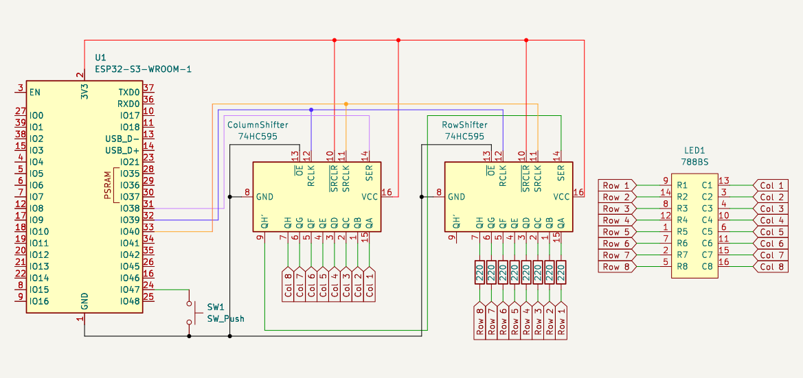
Initially I had trouble making sense of this as well, but after staring at it for long enough, I got it down. A part was drawn/maybe I picked the wrong schematic and that threw me off for a while.
The pins are organised in a way for legability. They do not reflect the actual ordering of the pins. The numbers in the red are the actual pin numbers.
Part List
| Amount | Part Name |
|---|---|
| 1 | ESP32-S3-WROOM-1 |
| 2 | 74HC595 Shift Register |
| 1 | 788BS 8x8 LED Matrix |
| 8 | 220Ω Resistor |
| 1 | Pushbutton (SW_Push) |
On The Breadboard
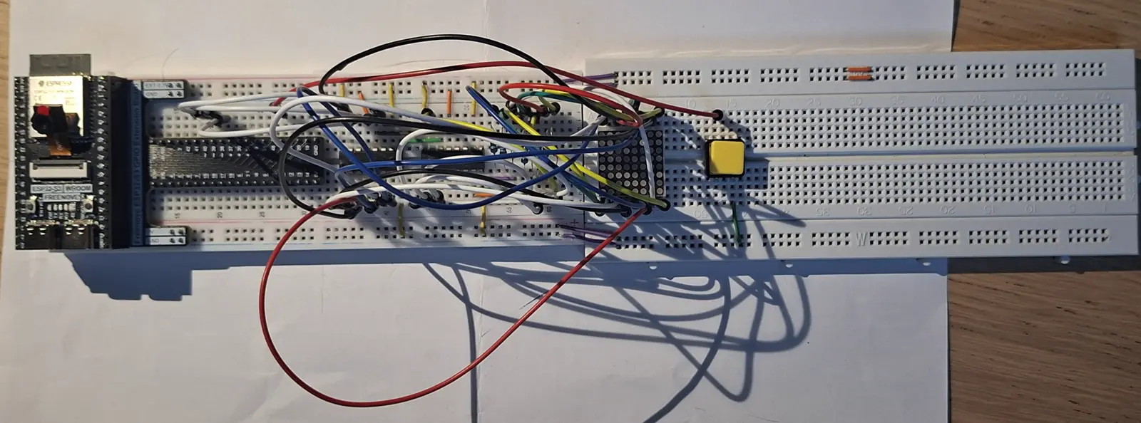
This is how it looks all wired up. Its a bit of a mess but it not thatttttt bad… I promise it looks better in person…
How It Works
In my opinion, the most confusing aspect of this project is getting the 788BS LED matrix to work. Its a bit more complex compared to using an LCD1602-I2C.
788BS
The 788BS is a common anode LED matrix. What this means that all the LEDs on a row are connected and you choose what column u want to modify by setting it to low and the rest to high. This creates a way for the current to flow. To display the full image, the columns are scanned across in a sequential order. But it happens so quickly that our brain just sees the full image, instead of individual columns.
Internals
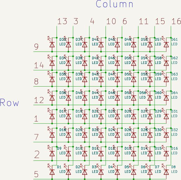
Below is how the internal of the 788BS is structured. It is a matrix of LEDs. You see that the entire row and column is selected at each time.
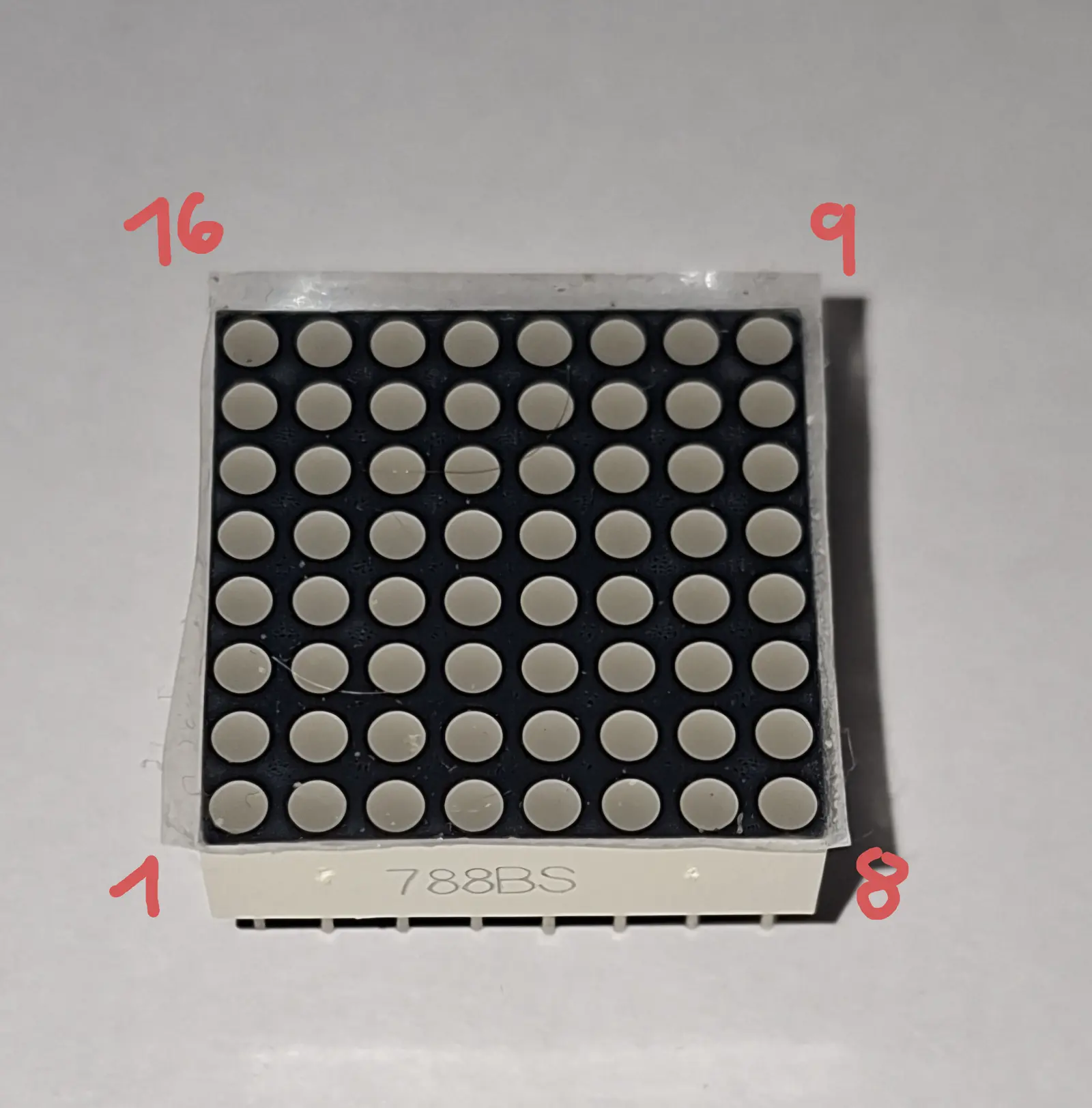
Pin Layout
The pin layout can be a bit confusing, they are ordered like this below.
Datasheet
To see more datails of the 788BS, I’ve linked its datasheet below. This goes into more detail on how its structured, as well as other details such as soldering conditions and the wavelength of the colour emmited.
Displaying an Image
You declare the image column by column, like seen below.
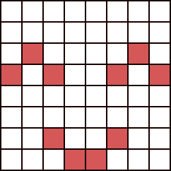
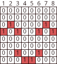
| Column | Binary | Hexadecimal |
|---|---|---|
| 1 | 0001 0000 | 0x10 |
| 2 | 0010 0000 | 0x20 |
| 3 | 0001 0010 | 0x12 |
| 4 | 0000 0001 | 0x01 |
| 5 | 0000 0001 | 0x01 |
| 6 | 0010 0001 | 0x21 |
| 7 | 0010 0000 | 0x20 |
| 8 | 0001 0000 | 0x10 |
uint8_t data[8] = { 0x10, 0x20, 0x12, 0x01, 0x01, 0x21, 0x20, 0x10};Bonus
You can display characters as well. With enough characters you can even create a sentence! By scrolling the characters across you can make marquee, the ones you see on the news channels.